Cornering Aerodynamics CFD Model
Master's thesis · Formule ETS · ÉTS
This thesis builds a steady-state cornering model in a rotating reference frame and validates it against wind tunnel, track and published LES within 6% or discrepancy.
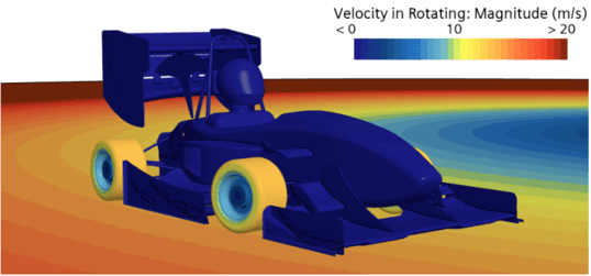
Formule ÉTS has been designing aerodynamic packages since 2010, and the method never changed: simulate the car in a straight line, on a half-model, assuming perfect symmetry. That model correlates well — under 4% against wind tunnel data. It also describes a condition the car spends very little of a lap in.

On an FSAE circuit, aerodynamics earns its keep in the corners — and the corners are where the lap actually is. The skidpad event is nothing but a corner.
Yet the tool the team designed with could not represent one: a symmetric half-model cannot be yawed, rolled or steered. The package was being optimized for the only situation in which its exact shape barely matters.
The stakes are not marginal. The aerodynamic package is worth roughly 51 points at competition and up to 10% of performance on skidpad, autocross and endurance — the three events dominated by corners.
Simulating a corner without paying for a transient
The obvious approach — a sliding mesh dragging the car around a circular path — is expensive enough to be unusable inside a design cycle. Instead, the whole domain is placed in a non-inertial, rotating reference frame. The car stands still, the world turns around it, and a steady-state RANS solve captures the cornering flow field. The price is two extra source terms in the momentum equation — Coriolis and centrifugal — for an angular velocity about the corner centre:
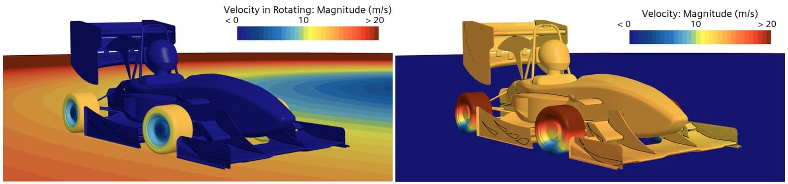
Turbulence is closed with SST. The car’s attitude in the corner — steering, body slip, roll — is not a free parameter: it comes from a Pacejka tyre model feeding the simulation as boundary conditions. That side of the work has its own write-up in the tyre model project.
Validation 1 — asymmetric runs in the wind tunnel
A cornering model cannot be validated in a tunnel — no student-accessible facility can put a car in a sustained corner. What a tunnel can do is yaw and roll the model, which isolates the asymmetric behaviour a cornering flow field depends on. Those runs came from the wind tunnel correlation campaign, where the full facility, methodology and force-coefficient results are documented.
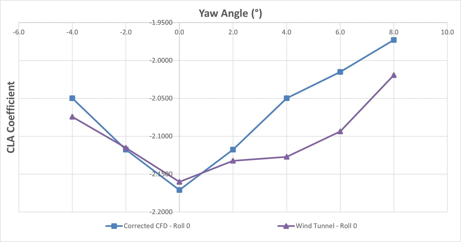
Downforce against yaw holds up well, despite asymmetric behaviour in the tunnel itself. That asymmetry traces to transient effects around the DELTA-25 aero package — amplified by the large separations that appear at high yaw — and to the simple fact that a hand-built prototype is never perfectly symmetric.
The agreement is strong enough to serve as the founding comparison for studying asymmetric effects in CFD, which is precisely what the cornering model needs.
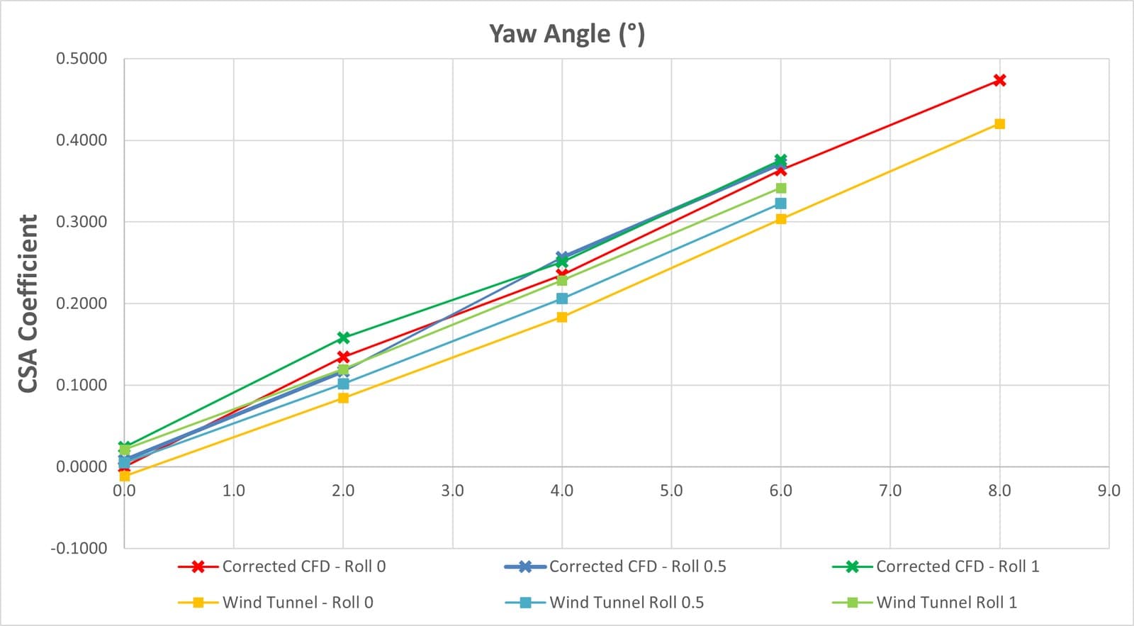
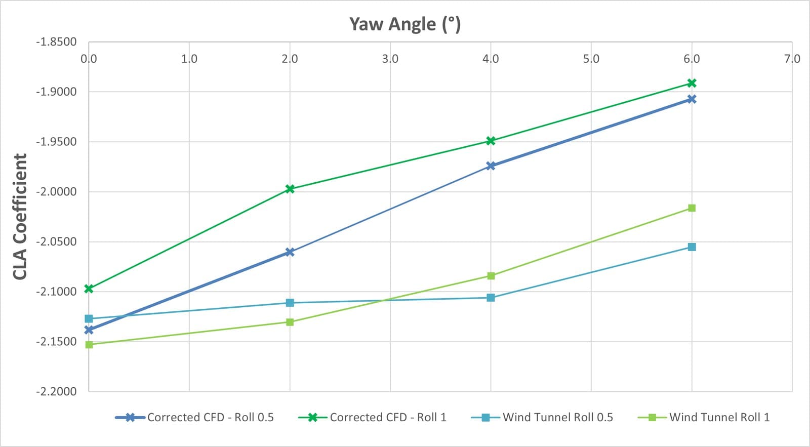
Two findings matter for the cornering work. Yaw dominates roll in setting side force, which justifies treating yaw as the primary asymmetric variable. And roll is where the model is weakest: it substantially under-predicts downforce at high yaw, traced to local mesh error under the very small car-to-ground clearance, and to the balance supports used in the tunnel. Knowing which of the two the model handles badly is what makes it usable anyway.
Validation 2 — against the straight-line model
At a large enough radius the cornering and straight-line models should converge. They do, which is the first sanity check that the rotating frame behaves.
| Model | C_L·A | C_D·A | Aero balance (front) |
|---|---|---|---|
| SLSM — straight line | −3.255 | −1.318 | 43.36% |
| CSM — cornering | −3.346 | −1.367 | 40.59% |
| Difference | 2.81% | 3.73% | 6.39% |
Validation 3 — against published LES
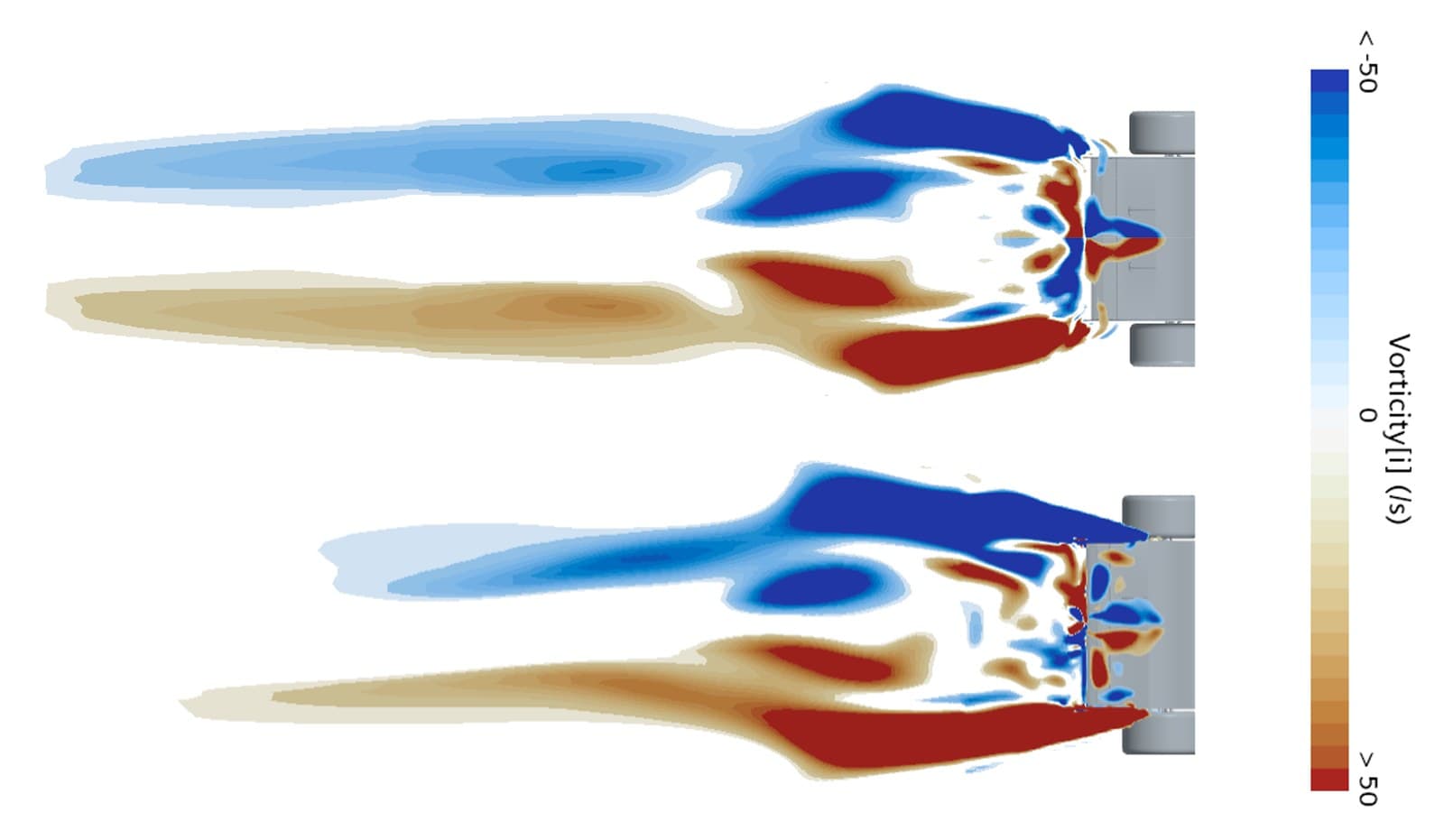
This is the result that matters most. Keogh’s large-eddy simulations of Ahmed bodies in curved flow predict a 19.2% drag rise for a corner of radius five times the vehicle length. The steady RANS cornering model returns 20.63% — a 1.4-point gap against LES, at a fraction of the cost.
Is it actually usable?
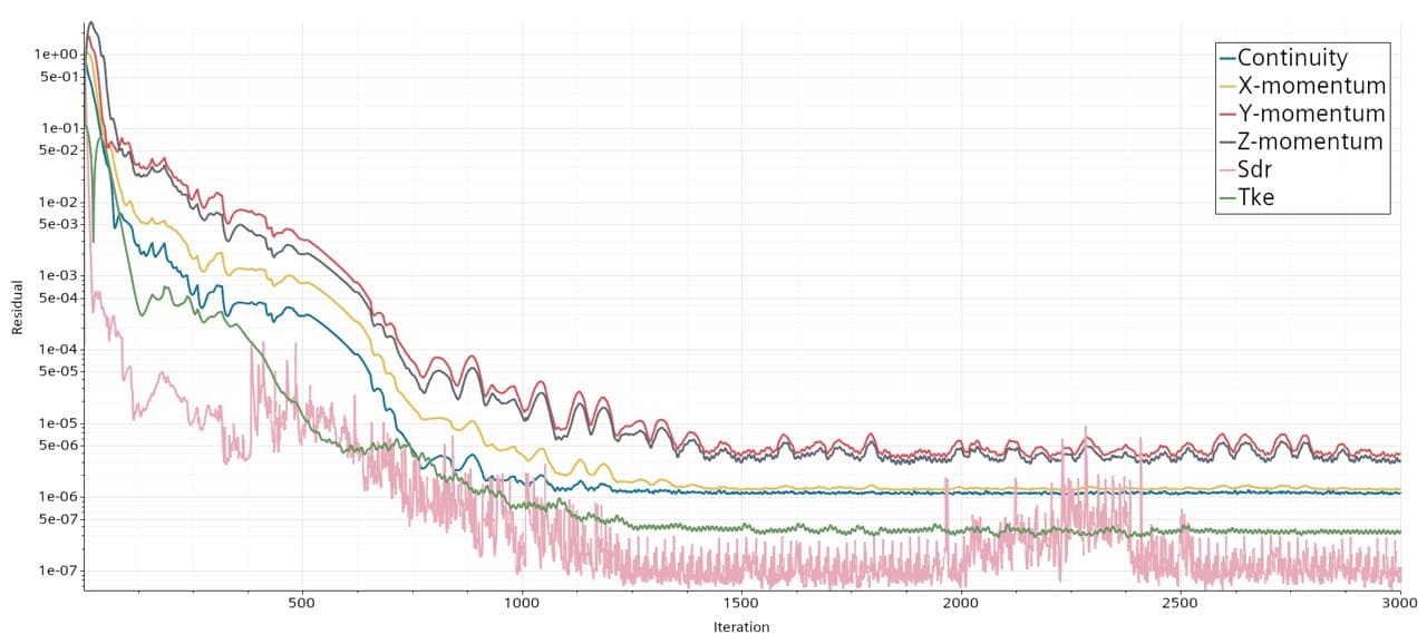
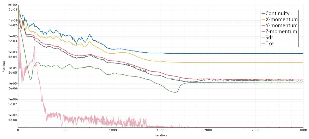
Both solutions converge to the same order, so the cornering model costs no more confidence than the one the team already trusted. It is finished enough to sit inside a real development cycle: future cars can be shaped against cornering conditions from the first design iteration rather than inheriting a straight-line optimum and discovering its cost in the corners — on a package already worth roughly 51 points at competition.
What it does not do
A steady-state model applied to intrinsically unsteady flow has limits worth stating plainly. The wind tunnel has no rolling road, so ground effect could not be validated properly. The vehicle dynamics model accounts only for lateral forces. Transient corner phases — braking, rotation, re-acceleration — stay out of reach until the model moves to URANS or DES and gains a four-degree-of-freedom description of the suspension.
Master’s thesis in Aerospace Engineering, École de Technologie Supérieure, defended 11 August 2026. Supervised by Giuseppe Di Labbio, co-supervised by Simon Joncas. The full document, the aerodynamic maps from both models and the wind tunnel test plan are on the Archives page.