Tire Model of a FSAE Prototype
Vehicle Dynamics Engineer · Formule ETS
A Pacejka Magic Formula tyre model fitted to Hoosier 16×7.5-10 R20 data below 30 N RMSE, generalised across vertical load and closed into a friction ellipse for lap-time simulation and cornering dynamics analysis.
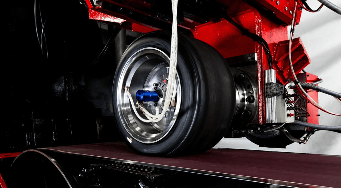
As part of the cornering aerodynamics and lap time simulation projects, it was necessary to create a lateral tyre model that would allow for the calculation of the steering angles and sideslip angle to input into the CFD model. Later, this tyre model was re-worked to include longitudinal forces, accelerations and establish a friction ellipse to use in the lap time simulation.
Caution: all data, values and results hereafter have been offset to preserve confidentiality tied to the FSAE Tire Test Consortium. The methodology is however valid and gives good results when used with the data found on the FSAETTC website.
Raw data
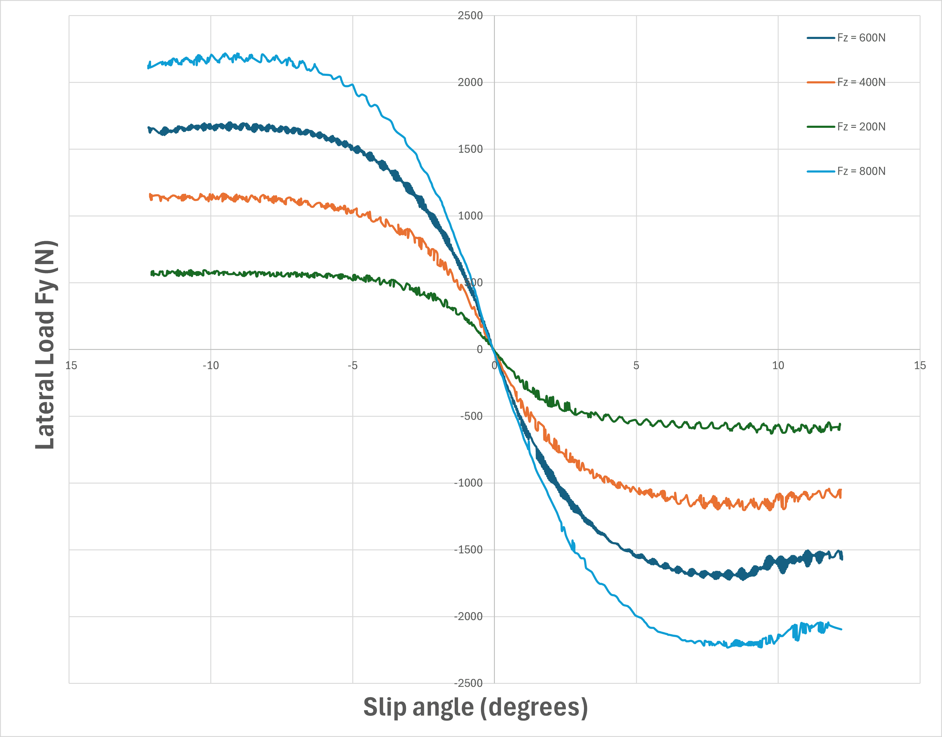
Raw tyre data was extracted from the private files of the FSAE Tire Test Consortium — a volunteer-managed organization of member schools who pool their financial resources to obtain high-quality tire force and moment data targeted at Formula SAE and Formula Student competitions. The FSAE TTC is organized by Milliken Research Associates, and the tests are run at the Calspan Tire Research Facility in Buffalo, NY.
The particular tyre this model is based on is the Hoosier 16x7.5-10 R20 compound present in Round 9 of testing. Most of the exact data remains undisclosed here, given the participative nature of the TTC and the need to fund it to gain access.
The first objective was to extract the data from the run files provided by the TTC, which meant filtering out some parameters to obtain the necessary curves.
Curve fitting the Magic Formula
The second step was to curve fit this raw data for each Fz load case following the 1996 edit of Pacejka's Magic Formula, defined by:
where D is the peak factor, C the shape factor, B the stiffness factor, E the curvature factor, Sₕ the horizontal shift, Sᵥ the vertical shift, α the slip angle and κ the slip ratio.
The curve fitting was achieved through a Python script to a root mean square error below 30 N. It was performed on multiple Fz load cases for both the lateral and longitudinal Magic Formula, to then create a general all-Fz approximation for the range of vertical loads experienced by our prototype — from 400 N to upwards of 1000 N.
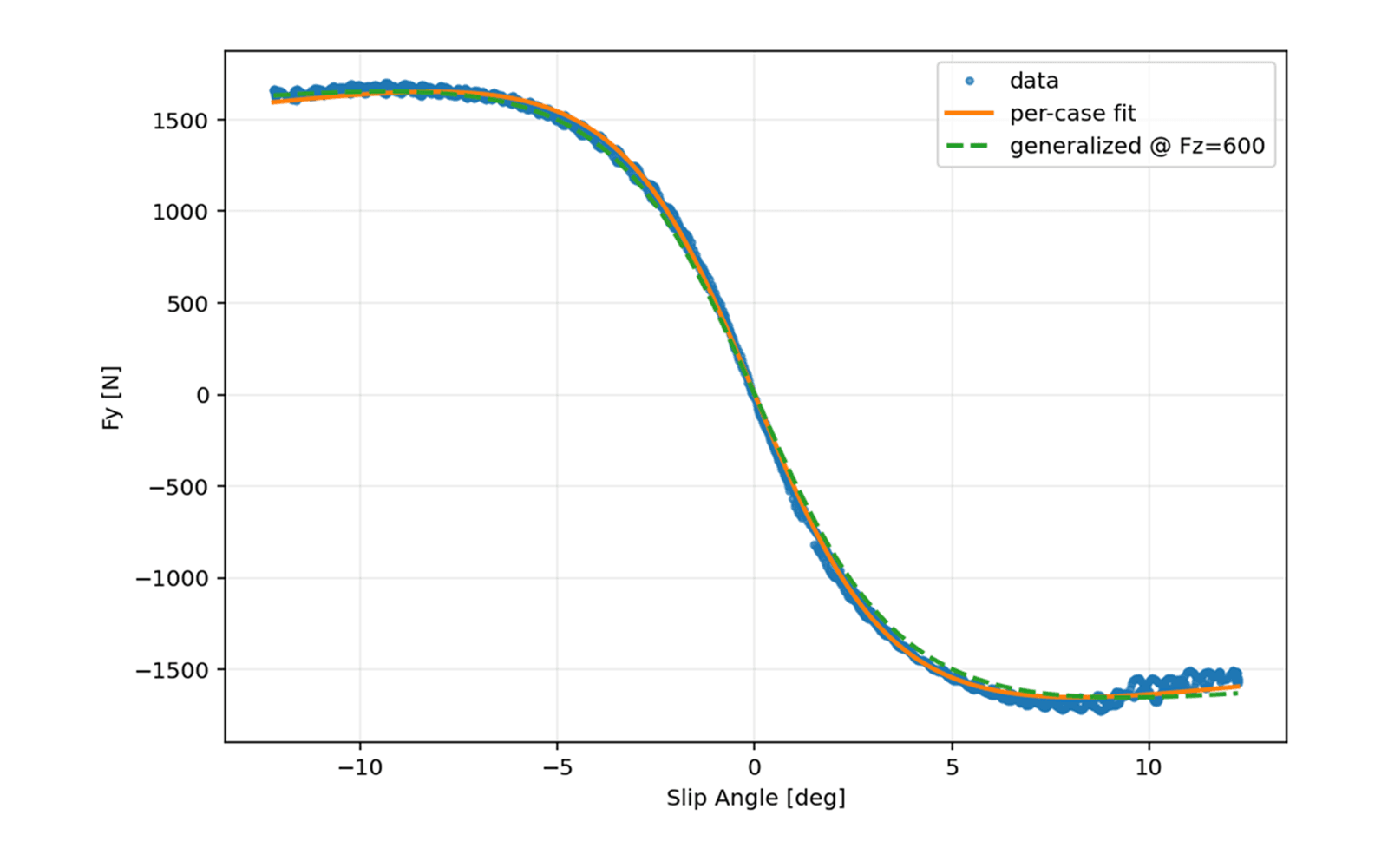
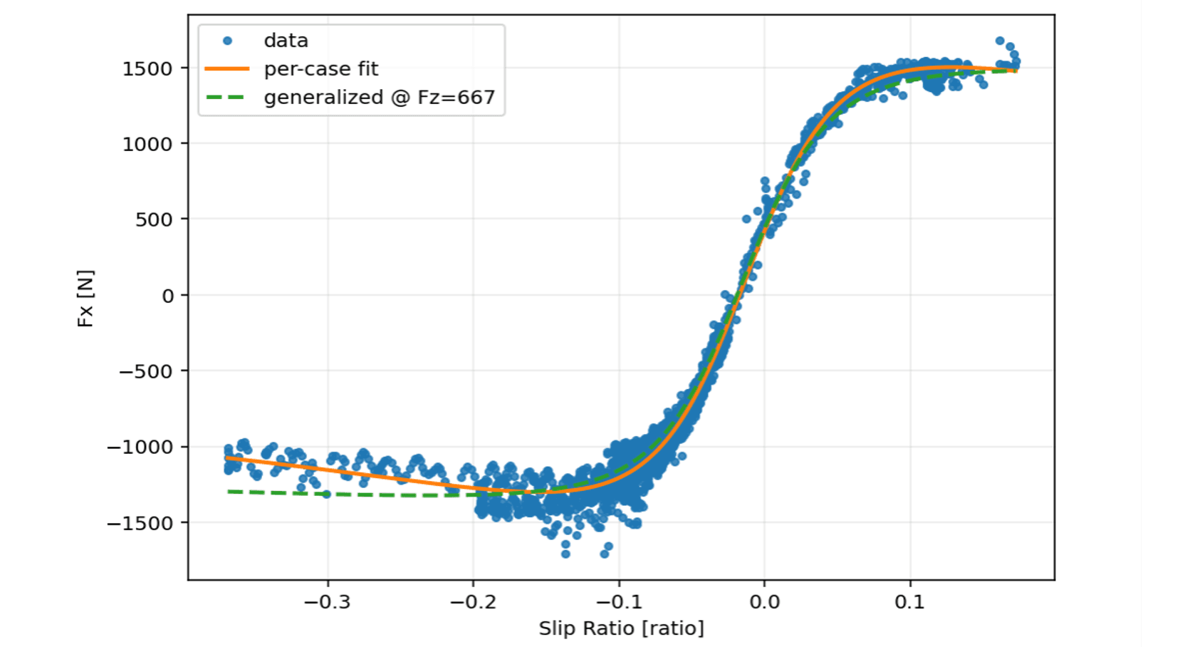
The general formulas are created by making the Pacejka coefficients load-dependent, rendering them B(Fz), C(Fz), D(Fz), E(Fz), Sₕ(Fz) and Sᵥ(Fz). For the lateral Magic Formula we assume Sₕ = Sᵥ = 0. Those generalized formulas allow the plotting and calculation of any Fz case.
From coefficients to usable loads
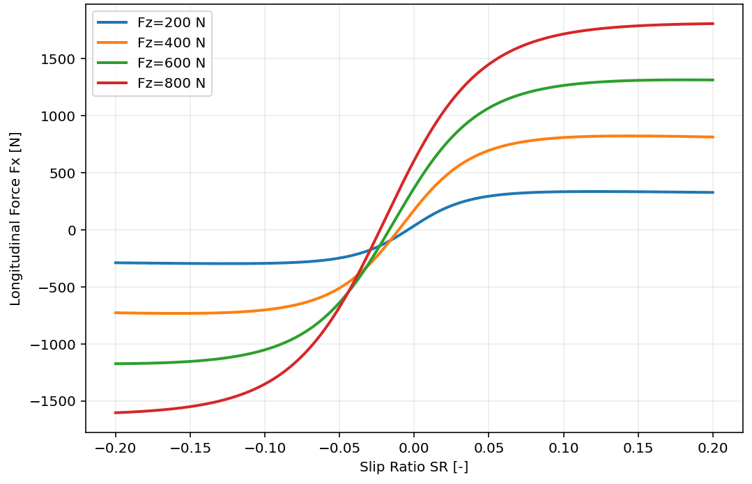
From here we can compute any lateral or longitudinal load from the two Magic Formulas, assuming we know the vertical load and the slip angle or ratio.
Knowing the load is straightforward on an FSAE car: we know the aerodynamic coefficients across a wide operating range — ride height, roll, pitch, yaw — and the weight of the car.
Knowing the geometry and properties of the suspension, we can also model the load transfer and calculate exactly the load experienced by a tire in any condition.
The slip angle or ratio, however, is mainly tied to driver ability and introduces a degree of randomness in how the car actually reacts. In a simulation we can either assume a perfect driver who maximises tire load at every moment, or introduce a thresholded random variable to account for driver skill. Either way the goal is to fix the slip angle against other variables so the Fx/Fy computation stays straightforward.
Closing the friction ellipse
Whether we assume a perfect or a human driver, the formulas give a theoretical maximum for Fy and Fx that we can use to build a friction ellipse. The prototype being a four-wheel-drive electric vehicle with almost exclusively regenerative braking, we assume forward and backward Fx are equivalent — producing a far more genuinely elliptical shape than the asymmetric ellipses usually seen. Ours is defined by:
Similarly, we can produce optimal slip angle against vertical load correlations, or maximum lateral force against vertical load graphs, that speed up the computations inside a lap time simulation.
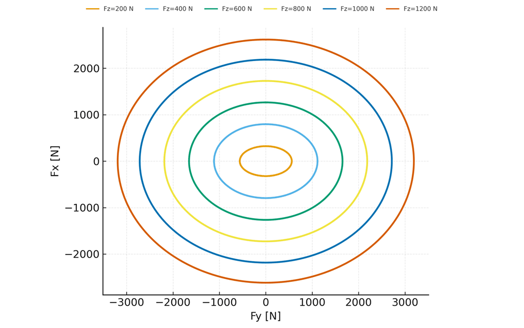
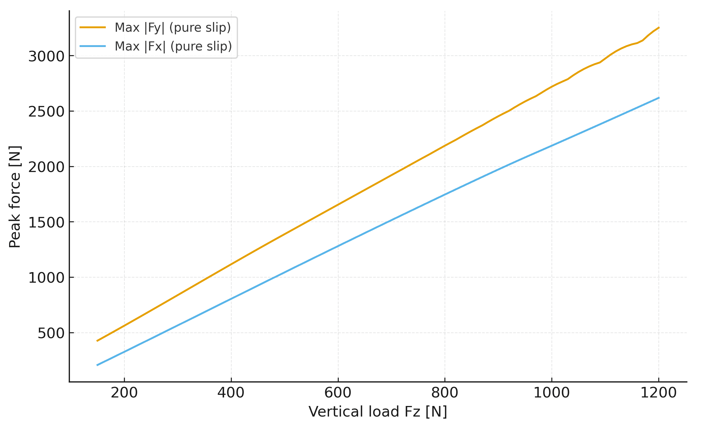
The combined-slip approach a friction ellipse offers gives more realistic results for the loads the tire generates, and a more thorough tire model raises the fidelity of the lap time simulation. The key is for the solver to catch the vertical load experienced by the tire and the split between longitudinal and lateral force over the segment being studied. From that we can compute a realistic longitudinal and lateral acceleration on the car.
What it deliberately ignores
Tires are complex, and against that complexity this model is simple. It does not yet account for pressure effects, temperature effects, camber angles or surface roughness. All of those — a Pacejka 5.2 or 6.2, for instance — remain to be integrated for a more precise simulation. But since the lap time simulation focuses on the impact of aerodynamics rather than full-car behaviour, the simpler model is the right trade.
For now, this model computes steering and sideslip angles for the cornering aerodynamics project, and provides the basic tire modelling behind the aerodynamics-focused lap time simulation.