Initial Hybrid Rocket Engine Modeling
Propulsion CFD Engineer · ROCKÉTS
A CFD simulation of paraffin–N2O combustion in a hybrid rocket engine, correlated to live-fire and in-flight data to within 3%.
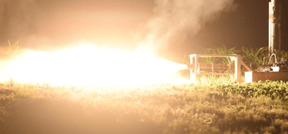
As a side project, I was asked by the ÉTS Student Rocketry team, RockÉTS, to simulate, analyze and optimize their home-made hybrid rocket engine (thereafter HRE) with CFD methodologies. The challenge of this project lied in modeling the combustion phenomenas specific to the function of HREs. Specifically, RockÉTS’ HRE works off the chemical reaction between Nitrous Oxide (NOS) and paraffin wax (C31H64) through complex pyrolysis and carbon decomposition mechanisms. The paraffin being a solid, some assumptions had to be made to simplify this problem, and create a RANS 2D-Axisymmetric baseline before scaling the model to DES or LES methods in 3D space.
This section explains the different steps towards modeling a HRE, and serves as introduction for further rocket combustion work.
Pana Hybrid Rocket Engine
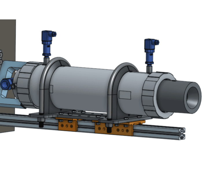
Pushed by the desire for innovation and after years of using commercial solid-fuel rocket engines, the RockÉTS student club began the design of a homemade rocket engine to compete in the SRAD (Student Researched and Designed) category of rocketry events.
Started in 2018, the Pana program aimed at designing a hybrid rocket engine that would power future rockets manufactured by the RockÉTS Student team. After 7 years of development, Pana made its debut at the 2025 IREC event but suffered a mechanical failure before its launch. However, multiple static fire test of both the lab-scale and rocket-scale prototypes of the engine have been successful, and allowed to gather sufficient data to validate a CFD model of the combustion. The combustion process involves an industrial-grade paraffin wax (C31H64) and nitrous oxide (N2O) that brings the thrust of this motor upwards of 4kN with a 7 seconds burn-time, that would theoretically bring RockÉTS’ latest rockets to speed upwards of Mach 2.
The first objective of this project is to provide a first modelization of Pana, by recreating the principal features of the engine in a simplified setting to prepare for CFD integration. Pana can be decomposed in several parts, each of them being subject to optimization to modify the engine’s performance.
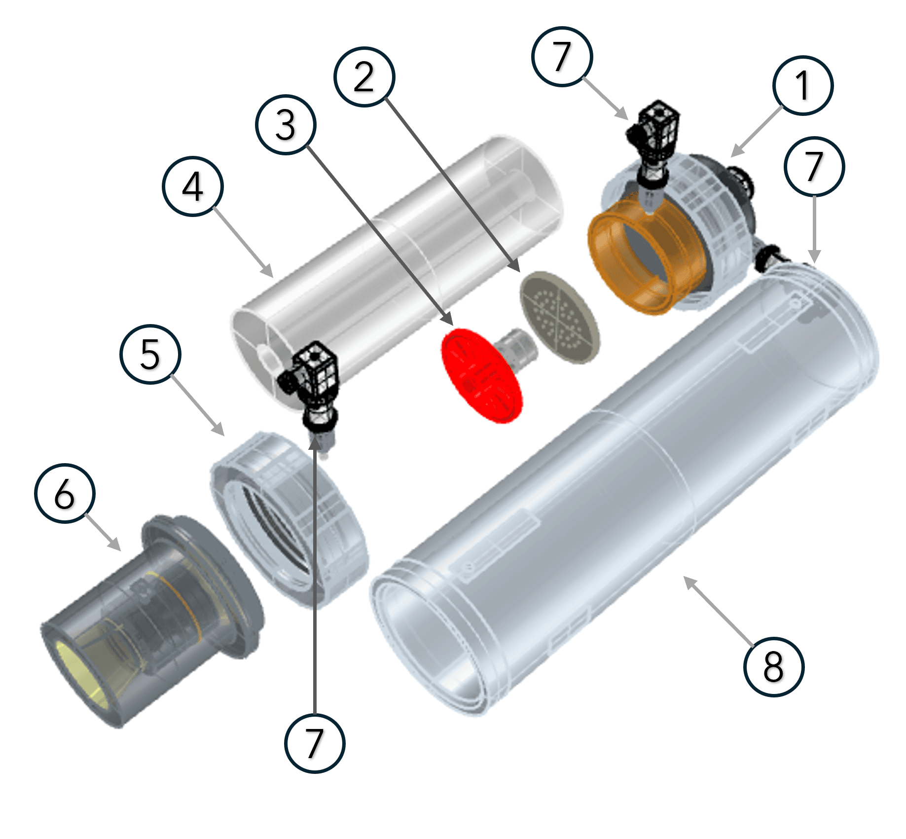
- 1. Pre-injection Chamber — the nitrous oxide is vaporized from the tank into this chamber before being injected in the combustion chamber.
- 2. Injector Plate — the nitrous oxide is injected through optimized holes to improve the mixability of the nitrous oxide with the parrafin vapors.
- 3. Engine Starter — a fire starter that ensures the beginning of the pyrolysis process of the paraffin wax and the ignition of the engine.
- 4. Fuel Grain Cell — a solid piece of paraffin wax with one or more ports for the nitrous oxide based mixture to flow through.
- 5. Post-combustion Chamber — a chamber to reduce the flow velocity of the gases and reduce the loss of nitrous oxide in the exhaust.
- 6. Exhaust Nozzle — an optimized shape exhaust to accelerate the gases to supersonic velocities and produce an increased thrust from the combustion while reducing over-expansion and under-expansion shocks.
- 7. Pressure Sensors — (only on the static fire versions of the engine) allow for the precise measure of pressure differentials within the engine, resulting in precise correlation data.
- 8. Engine Casing — a thermo-mechanical resistant cover to accomodate the extreme temperatures and pressure within the combustion chamber.
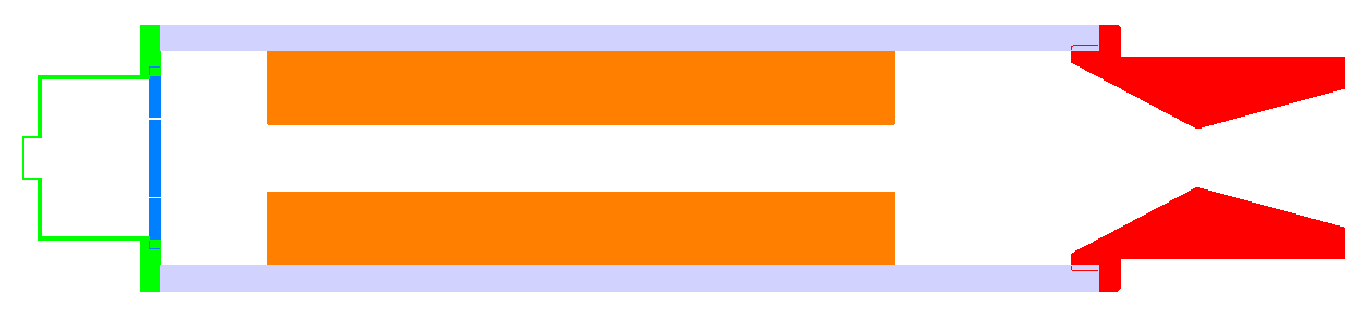
The precise Pana assembly is very complex and follows high standards of manufacturing to ensure the success of every static fire test and rocket launch with this engine. However, this assembly is too detailed for CFD simulation purposes as is. The first step towards the simulation of the combustion process resides in simplifying the geometries and features of this assembly. This step will ensure the quality and simplicity of the mesh, resulting in a more robust and stable solution down the line. Thereafter is a longitudinal section view of the CFD assembly of Pana, color coded to differentiate important parts that will have different boundary conditions or optimization targets.